MXR Phase 90 - Analog modelling [C++ JUCE]
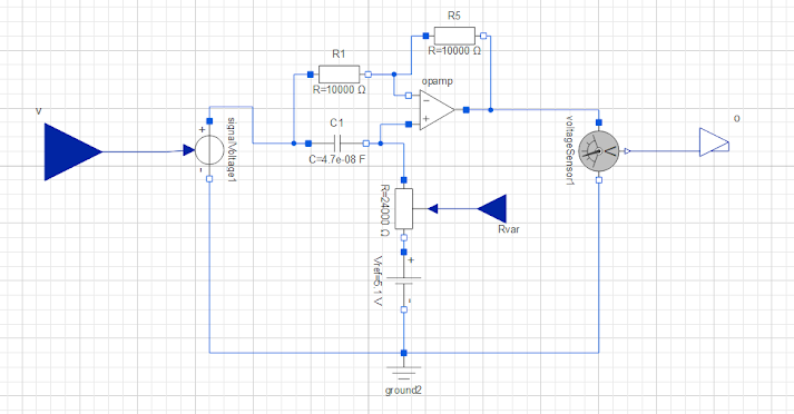
The phase shifting stage comprises four cascaded op-amp-based all-pass filters. Each filter introduces a 90° phase shift at the cutoff frequency of the low-pass filter (which is 45°). Importantly, the magnitude response remains constant.
By connecting two of these networks in series, the phase at the Phaser frequency is shifted to 180° (90° + 90°). When the processed signal with the 180° phase-shift is added to the original signal, amplitude cancellation occurs only at Phaser frequency, creating a notch at this frequency.
Consequently, introducing series pairs of Phase Shifting Units generates additional notches: 2 stages yield 1 notch, 4 stages result in 2 notches, and so forth. This effect is further enhanced when the notches shift in frequency, easily achievable by modifying the resistor values in the RC chain.
Modulation
The original MXR Phase 90 circuit alters the notch frequencies by adjusting the resistance values in each all-pass filter. This is achieved using Voltage-Controlled Resistances (VCR) employing FET transistors. A low-frequency oscillator is connected to the base of these transistors to enable frequency modulation.
In this approach, I refrained from modelling the transistors due to their nonlinear nature, as explained in the Steiner-Parker post. Instead, I implemented a sine oscillator in C++ to modify the resistance values. Such simplifications are commonly employed in analog modeling VSTs to optimize resources efficiently.
Additionally, it's worth noting that this all-pass filter can be easily implemented using a feed-forward network if one has knowledge of DSP. Indeed, the primary focus remains on showcasing the approach to model a linear circuit, as highlighted in the previous post.
In future posts, I would like to delve into the modeling of non-linear components or non-ideal linear components, which involves employing more advanced techniques such as Black Box models.
Implementation
For the implementation, I followed the same approach outlined in the Steiner-Parker modeling post. I highly recommend reading that post for a more in-depth understanding.
I obtained the differential equations of a phase shift unit (all-pass filter) using Mathematica and then applied the Heun method. In this case, the implementation is simplified because there is only one capacitor involved(1st Order system). In the C++ JUCE implementation, I created four stages of the all-pass filters in the process block, stored them in a buffer, and finally mixed them with the clean signal, as explained at the beginning of the post. Here is the commented code.
void PhaserAudioProcessor::processBlock (juce::AudioBuffer& buffer, juce::MidiBuffer& midiMessages)
{
    juce::ScopedNoDenormals noDenormals;
    auto totalNumInputChannels  = getTotalNumInputChannels();
    auto totalNumOutputChannels = getTotalNumOutputChannels();

    juce::AudioBuffer phaserBuffer(totalNumInputChannels, buffer.getNumSamples()); // Create a buffer for the phase shift chain
    phaserBuffer.clear();

    juce::AudioBuffer LFObuffer(totalNumInputChannels, buffer.getNumSamples()); // Create a buffer to store the LFO samples
    LFObuffer.clear();

    for (auto i = totalNumInputChannels; i < totalNumOutputChannels; ++i)
        buffer.clear (i, 0, buffer.getNumSamples());

    for (int channel = 0; channel < totalNumInputChannels; ++channel)
    {
        auto* channelData = buffer.getWritePointer (channel);

  		// Store the LFO samples in buffer
        ptrLFO[channel]->processLFO(LFObuffer.getWritePointer(channel), *parameters.getRawParameterValue("FREQ_ID"));

  		// 4 All-pass Filter stages
        ptrPhaser1[channel]->processPhaser(channelData, phaserBuffer.getWritePointer(channel), buffer.getNumSamples(), getSampleRate(), LFObuffer.getReadPointer(channel));
        ptrPhaser2[channel]->processPhaser(phaserBuffer.getWritePointer(channel), phaserBuffer.getWritePointer(channel), buffer.getNumSamples(), getSampleRate(), LFObuffer.getReadPointer(channel));
        ptrPhaser3[channel]->processPhaser(phaserBuffer.getWritePointer(channel), phaserBuffer.getWritePointer(channel), buffer.getNumSamples(), getSampleRate(), LFObuffer.getReadPointer(channel));
        ptrPhaser4[channel]->processPhaser(phaserBuffer.getWritePointer(channel), phaserBuffer.getWritePointer(channel), buffer.getNumSamples(), getSampleRate(), LFObuffer.getReadPointer(channel));

  		// Mix the clean signal with the Phase shifted signal
        ptrMix[channel]->processMix(channelData, phaserBuffer.getWritePointer(channel), channelData, buffer.getNumSamples(), *parameters.getRawParameterValue("MIX_ID"));
    }
}
Thank you for reading!


